You’re peering into a hidden universe—cells dividing, bacteria gliding through fluid, intricate plant tissues—all revealed by the compound microscope. But to truly unlock its potential, you need more than just power; you need to understand the compound microscope diagram explained in full. Every labeled part plays a crucial role in delivering a sharp, magnified image. Whether you’re a student preparing for a biology lab, a teacher guiding young scientists, or a researcher analyzing specimens, knowing how each component works is essential.
This guide breaks down the compound microscope diagram step by step, explaining not just what each part is called, but how it contributes to image clarity, focus, magnification, and safety. From the base to the eyepiece, we’ll walk through structural and optical systems, trace the path of light, calculate magnification, and share expert tips for optimal use. By the end, you won’t just recognize the parts—you’ll know how to use them like a pro.
Base and Arm: The Foundation of Stability
Before diving into optics, let’s start with the physical support system—these parts keep your microscope steady and safe during use.
Base Anchors the Microscope and Powers the Light
The base is the heavy, bottom section that provides balance and houses key electrical components. It typically contains the illuminator (LED or halogen bulb), on/off switch, and brightness control. Its weight prevents tipping, especially when adjusting the stage or focusing at high power. Always carry the microscope with one hand on the arm and the other supporting the base to avoid dropping or jarring delicate internal optics.
Arm Connects and Supports the Optical System
The arm is the curved or straight structural bridge between the base and the head. It holds the body tube, nosepiece, and stage in precise alignment. In binocular models, some arms include an inclination joint for viewing comfort, but tilting the microscope during use is discouraged—it can cause slides to slip or oil to spill. The arm also serves as the primary carrying handle, so grip it firmly whenever moving the instrument.
Stage and Specimen Handling: Precision Matters
This is where your sample goes—the stage and its accessories ensure your slide stays secure and movable for detailed inspection.
Stage Holds the Slide Over the Light Path
The stage is a flat platform (usually 120 mm × 120 mm) with a central aperture—a circular opening that allows light to pass up through the specimen. Stages come in two types:
– Plain stage: Uses stage clips to hold the slide.
– Mechanical stage: Allows controlled movement via knobs—critical for high-magnification work.
Always center your specimen over the aperture before viewing.
Stage Clips Keep the Slide in Place
On basic models, spring-loaded stage clips secure the glass slide. While simple, they require careful handling. Avoid pushing the slide manually during observation—especially at high power—since even a tiny nudge can shift the field of view completely.
Mechanical Stage Enables Accurate Navigation
For precision, most advanced microscopes feature a mechanical stage controlled by two knobs:
– One adjusts left-right (X-axis)
– One adjusts forward-backward (Y-axis)
This system lets you scan across a slide methodically, essential for locating specific cells or tracking structures in histology or microbiology.
Rack Stop Protects Lenses and Slides
This often-overlooked safety feature limits how far the stage can rise. It prevents the 40x or 100x objective from crashing into the slide during coarse focusing. The rack stop is factory-set and should never be tampered with. Ignoring it risks cracked slides, scratched lenses, or misaligned optics—costly mistakes in any lab.
Optical System: How Magnification and Clarity Are Achieved
Now let’s dive into the heart of the microscope—the lenses and light control systems that make tiny details visible.
Eyepiece Delivers the Final Magnified View
The eyepiece (ocular lens) is where you look—typically offering 10x magnification. It further enlarges the image formed by the objective lens. Some models include a pointer or graticule (measuring scale) inside the eyepiece. In binocular microscopes, a diopter adjustment ring compensates for vision differences between your eyes, ensuring both views are sharp.
Pro Tip: Focus with both eyes open to reduce strain during long sessions.
Body Tube Maintains Optical Alignment
This metal cylinder connects the eyepiece to the nosepiece, maintaining a standard optical tube length of 160 mm—critical for proper magnification. Any misalignment (from impact or dust) can result in blurry or dim images. Never touch the inside of the tube or allow debris to enter.
Objective Lenses and Nosepiece: The Powerhouse of Magnification
These are the core of the microscope’s imaging capability. Understanding their roles—and limitations—is key to effective use.
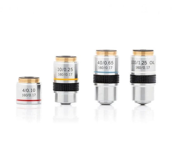
Objective Lenses Provide Step-by-Step Magnification
Mounted on the nosepiece, standard objectives include:
| Magnification | Name | Use |
|---|---|---|
| 4x | Scanning objective | Locate specimen, wide view |
| 10x | Low power | General observation |
| 40x | High power (“High dry”) | Cellular detail |
| 100x | Oil immersion | Maximum resolution |
Each has a color-coded band:
– 4x → Red
– 10x → Yellow
– 40x → Blue
– 100x → White/Black
Higher magnification means shorter working distance—the 100x lens is only 0.1 mm from the slide.
Oil Immersion Lens Requires Special Technique
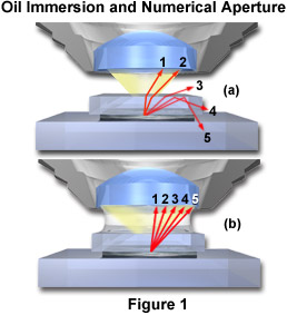
The 100x objective must be used with immersion oil (refractive index ~1.515). Without oil, light scatters at the air-glass interface, reducing resolution and clarity. Apply a small drop of oil directly on the slide before rotating the 100x lens into place. After use, clean the lens with lens paper and xylene or alcohol—never use regular tissue or fingers.
Warning: Never use 100x without oil. You’ll get a blurry image and risk damaging the lens.
Nosepiece Rotates Objectives Safely
The revolving nosepiece (turret) holds 3–5 objectives and clicks into alignment. Always rotate it by the turret ring, not the lenses. Forcing it can strip gears or misalign optics.
Illumination and Light Control: The Key to Clear Images
Even the best lenses fail without proper lighting. These components ensure your specimen is well-lit and high-contrast.
Illuminator Provides Bright, Consistent Light
Modern microscopes use LEDs (preferred) or halogen bulbs in the base. LEDs last over 50,000 hours, emit no heat, and offer daylight-balanced light (~5500K). Halogen bulbs are brighter but yellowish and hot—often requiring a blue filter to correct color. Older models use a mirror, but this is outdated and unreliable.
Condenser Focuses Light for Maximum Resolution
Located under the stage, the condenser (often an Abbe condenser) concentrates light into a cone that matches the objective’s numerical aperture (NA). It’s essential for magnifications above 400x. For best results, raise it to its highest position—just below the slide.
Iris Diaphragm Balances Contrast and Clarity
This adjustable ring controls the width of the light beam. Adjust it based on magnification:
– 4x–10x: 70–80% open
– 40x: 80–90% open
– 100x: Fully open
Too much light washes out detail; too little makes the image too dark.
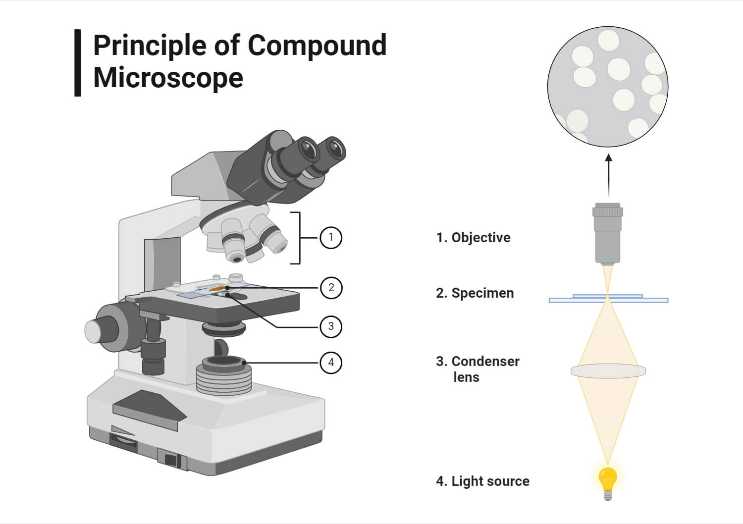
How the Image Is Formed: The Optical Path Explained
Understanding the light path helps troubleshoot blurry or dim views.
Light Travels from Base to Your Eyes
- Illuminator emits light upward
- Light passes through the aperture and into the condenser
- Condenser focuses light onto the specimen
- Light exits through the objective lens, forming a real, inverted image
- Eyepiece magnifies this into a virtual, highly magnified image
Note: The final image is inverted and reversed. Move the slide right, and the image moves left—this is normal.
Calculating Total Magnification: Simple Math
Multiply Eyepiece by Objective
[
\text{Total Magnification} = \text{Eyepiece (10x)} \times \text{Objective (e.g., 40x)} = 400x
]
| Objective | Total Magnification (with 10x eyepiece) |
|---|---|
| 4x | 40x |
| 10x | 100x |
| 40x | 400x |
| 100x | 1000x |
Fact: Beyond 1000x, you hit the diffraction limit of visible light (~0.2 µm). Higher magnification (e.g., 1500x) results in empty magnification—bigger but blurrier.
Focus Knobs: Coarse vs Fine – When to Use Which
Coarse Focus Knob: For Initial Focusing Only
Use only with 4x and 10x objectives to bring the specimen into rough focus. Never use it with 40x or 100x—risk of lens damage is high.
Fine Focus Knob: For Crisp Detail
Makes micron-level adjustments. After coarse focus, use only the fine knob at high power. In coaxial models, both knobs share a shaft for smoother control.
Best Practices for Safe and Effective Use
- Always start with 4x to locate your specimen
- Use coarse focus only at low power
- Adjust diaphragm per objective
- Clean lenses with lens paper only
- Store with 4x objective in position to protect higher lenses
- Never tilt the microscope during use
Advanced Features in Modern Microscopes
- Binocular models: Reduce eye strain with interpupillary and diopter adjustment
- Trinocular models: Add a camera for digital imaging
- LED illumination: Superior to halogen in lifespan and stability
- Abbe condenser: Required for 1000x resolution
Final Tips for Mastery
Understanding the compound microscope diagram explained is the first step. To master it:
– Label each part on your own microscope
– Practice focusing with prepared slides
– Adjust condenser and diaphragm for each magnification
– Teach others—explaining reinforces learning
With this knowledge, you’re not just reading a diagram—you’re learning to see the invisible.