If you’re searching for a microscope diagram with labeled parts, you’re not just looking for a picture—you’re trying to understand how this essential scientific instrument works. Whether you’re a student preparing for a biology lab, a teacher creating a worksheet, or a curious learner exploring cellular structures, knowing each component of a compound light microscope is crucial. This microscope diagram with labeled parts breaks down every key element, from the eyepiece to the base, explaining what it does, why it matters, and how to use it properly. By the end, you’ll be able to confidently identify all major components and understand how they work together to reveal the invisible world.
Structural Framework: Head, Arm, and Base
These three components form the skeleton of the microscope, ensuring stability, alignment, and safe handling.
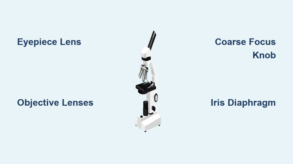
Head (Body Tube)
The head, also known as the body tube, houses the optical path between the eyepiece and the objective lenses. It maintains a fixed distance—typically 160 mm—called the optical tube length, which ensures accurate magnification and image clarity. In binocular models, the head may tilt or rotate to allow comfortable viewing angles during long observation sessions. Because it contains delicate internal optics, always avoid dropping or bumping the head.
Arm
The curved arm connects the head to the base and provides structural support. More importantly, it’s the correct place to grip when carrying the microscope. Always use one hand on the arm and the other supporting the base to prevent strain or accidental drops. On advanced models, the arm may include built-in controls like brightness dials or focus knobs for ergonomic access.
Base
The base is the foundation of the microscope, designed to be heavy and wide for maximum stability. It prevents tipping during use and protects internal components such as the illuminator, power switch, and circuitry that controls light intensity. Never place objects on top of the base, and keep it clean and dry to avoid electrical hazards. After use, store the microscope with the base facing outward for easy transport.
Optical System: How Light and Lenses Create Magnification
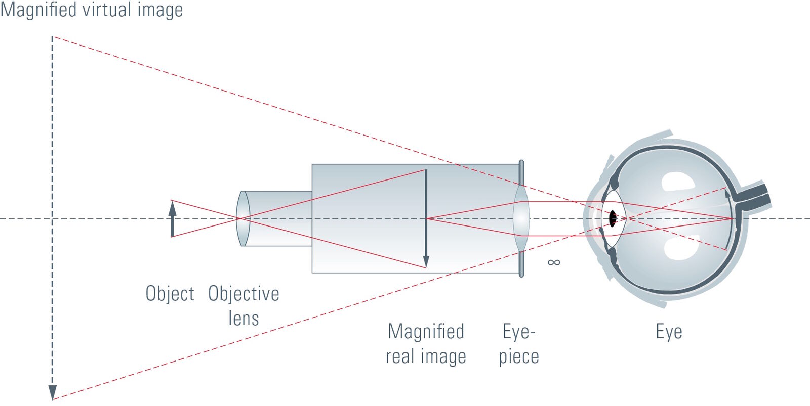
The magic of a microscope happens through its optical components, which capture and enlarge the image of tiny specimens.
Eyepiece (Ocular Lens)
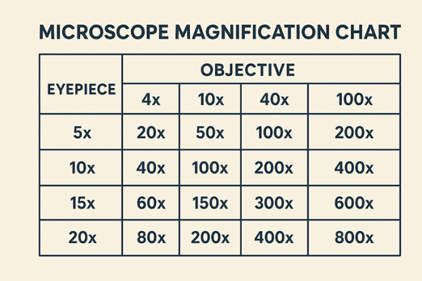
The eyepiece is where you look to see the magnified image. Most are labeled 10X, meaning they magnify the image tenfold. Some specialized models offer 5X or 15X eyepieces for different applications. Binocular microscopes have two eyepieces, allowing both eyes to view simultaneously, reducing eye fatigue. Never touch the lens surface with your fingers—use lens paper only for cleaning to avoid scratches.
Diopter Adjustment
Found on one eyepiece in binocular models, the diopter adjustment compensates for differences in vision between your eyes. To set it: close one eye and focus using the fine knob, then switch eyes and adjust the diopter until both views are sharp. This ensures a single, clear image without strain—essential for extended use.
Body Tube Function
Beyond structural support, the body tube ensures that light travels in a straight, uninterrupted path from the objective lens to the eyepiece. Any misalignment can distort the image or reduce resolution. In high-end models, the tube may rotate or incline for user comfort, especially in shared lab environments.
Nosepiece (Revolving Turret)
The nosepiece holds 3 to 4 objective lenses and rotates to switch between magnifications. Turn it gently until you hear a click, indicating that the lens is locked into position. Forcing the nosepiece can damage internal gears or misalign the lenses, leading to blurry images or difficulty focusing.
Objective Lenses: The Power Behind Magnification
Each objective lens provides a different level of magnification and resolution, allowing step-by-step exploration of microscopic details.
Scanning Objective (4X)
Color-coded red, the 4X objective offers the lowest magnification but the widest field of view. Use it first to locate your specimen on the slide. With a standard 10X eyepiece, total magnification is 40X, ideal for scanning large areas like tissue sections or whole organisms.
Low Power Objective (10X)
Marked with a yellow band, this lens provides 10X magnification. When paired with a 10X eyepiece, it delivers 100X total magnification, perfect for observing multicellular structures such as plant cells or small invertebrates.
High Power Objective (40X)
Identified by a blue or light blue ring, the 40X lens gives 400X total magnification with a 10X eyepiece. It reveals fine cellular details like nuclei and cytoplasmic structures. This lens is often spring-loaded, meaning it retracts slightly if it touches the slide, protecting both the lens and the specimen.
Oil Immersion Objective (100X)
The 100X objective, marked with a white or black band, requires immersion oil to function correctly. Without oil, light bends (refracts) as it exits the glass slide, reducing resolution. Place a small drop of oil directly on the slide, then rotate the 100X lens into place. Total magnification reaches 1000X, enabling visualization of bacteria and subcellular organelles. Always clean the lens immediately after use with lens paper and oil cleaner.
Focus and Slide Control: Precision for Clear Imaging
Accurate focusing and slide manipulation are critical for detailed observation.
Coarse Adjustment Knob
This larger knob moves the stage (or objectives) rapidly up and down. Use it only with the 4X and 10X objectives to bring the specimen into rough focus. Never use it with 40X or 100X lenses—doing so risks crashing the lens into the slide, which can crack the glass or scratch the lens.
Fine Adjustment Knob
The smaller knob makes tiny, precise movements. After coarse focusing, use the fine knob to sharpen the image—especially important at high magnifications. It allows you to distinguish fine details like cell membranes or bacterial flagella.
Stage and Slide Positioning
The stage is the flat platform where you place the microscope slide. It has a central aperture that allows light to pass through the specimen. Stage clips hold the slide in place, but for greater control, many microscopes feature a mechanical stage.
Mechanical Stage Operation
A mechanical stage uses two control knobs:
– One for left-right (X-axis) movement
– One for forward-backward (Y-axis) movement
This allows precise navigation across the specimen without touching the slide—especially useful at 400X or 1000X, where even slight movements shift the field of view dramatically.
Illumination System: Light for Clarity and Contrast

Proper lighting is just as important as magnification for producing a clear image.
Light Source (Illuminator)
Modern microscopes use LED bulbs in the base because they are energy-efficient, long-lasting, and produce minimal heat. Older models may use halogen or tungsten bulbs, while fluorescence microscopes require specialized lamps like mercury vapor. Always turn off the light when not in use to extend bulb life.
Condenser Function
Located beneath the stage, the condenser focuses light onto the specimen. It’s essential for high-magnification work (400X and above). If the condenser is too low, the image will appear dim or blurry. Adjust it so that light is concentrated exactly on the specimen area.
Diaphragm (Iris Diaphragm)
The iris diaphragm controls the width and intensity of the light beam. Closing it increases contrast—helpful for transparent specimens like unstained cells—but reduces resolution. Opening it improves clarity and resolution but may wash out faint details. Find the optimal balance for your sample.
Abbe Condenser Explained
An Abbe condenser is a high-performance lens with a numerical aperture (NA) up to 1.25, designed specifically for use with the 100X oil immersion objective. It often includes an integrated iris diaphragm and is standard on research-grade microscopes. Proper use of the Abbe condenser enables Köhler illumination, a technique that ensures even lighting and maximum resolution.
Safety and Adjustment Features
These components protect both the user and the instrument.
Rack Stop Importance
The rack stop limits how far the stage can rise, preventing high-power objectives from hitting the slide during focusing. It’s usually factory-set and should never be disabled. Bypassing it risks costly damage to expensive lenses.
Light Switch and Brightness Control
The light switch powers the illuminator, typically located on the base or arm. The brightness control (rheostat) adjusts light intensity. Always start with the brightness at minimum before turning on the microscope to prevent bulb burnout. Gradually increase it to suit your specimen.
Step-by-Step Microscope Operation
Follow this sequence for clear, safe use:
- Place the slide on the stage and secure it.
- Rotate the nosepiece to the 4X objective.
- Look from the side and lower the stage until the lens is near—but not touching—the slide.
- Look through the eyepiece and use the coarse knob to raise the stage until the image appears.
- Use the fine knob to sharpen the image.
- Switch to higher objectives one at a time, using only the fine knob for focusing.
Common Mistakes and How to Avoid Them
- Using coarse focus at high power: Risk of lens damage. Fix: Use only fine adjustment above 10X.
- Forgetting immersion oil: Results in blurry 100X images. Fix: Always apply oil before using 100X.
- Over-closing the diaphragm: Reduces resolution. Fix: Open it enough to maintain detail while enhancing contrast.
Maintenance Best Practices
- Clean lenses with lens paper only.
- Carry the microscope with arm and base supported.
- Store with the lowest objective selected and stage lowered.
- Keep in a dry, dust-free environment.
A microscope diagram with labeled parts is more than a study aid—it’s your roadmap to mastering one of science’s most powerful tools. Understanding each component empowers you to operate the microscope safely, achieve sharp images, and explore the microscopic world with confidence.