If you’ve ever explored the hidden world of cells, bacteria, or tissue structures in a biology lab, you’ve likely used a compound light microscope—a powerful instrument that reveals what the naked eye can’t see. Unlike simple magnifying tools, this microscope uses two lens systems and visible light to achieve high magnification, typically ranging from 40x to 1,000x. But how does it deliver such detailed images? The answer lies in its precisely engineered components, each playing a critical role in image clarity, focus, and usability.
Understanding the parts of a compound light microscope and their functions is essential for students, educators, and researchers alike. From adjusting the condenser for optimal contrast to switching to the 100× oil immersion lens for maximum resolution, every component contributes to imaging success. Whether you’re locating a single cell or documenting microscopic details with a camera, knowing how each part works ensures accurate observations and prevents costly mistakes. In this guide, we’ll break down all major components—structural, optical, mechanical, and illumination—explain their roles, and offer practical tips for effective use.
Base Ensures Stability and Houses Key Electronics
The base is the foundation of the microscope, designed to keep the entire instrument stable during use. Typically made of heavy metal or dense plastic, it prevents tipping and absorbs vibrations that could blur your view. Beyond physical support, the base contains crucial internal components: the illuminator (light source), power switch, and wiring. Always carry the microscope with one hand on the arm and the other under the base to protect internal electronics and maintain balance. A sturdy base isn’t just about weight—it’s about ensuring consistent, shake-free viewing.
Arm Provides Support and Safe Handling
The arm connects the base to the head and supports the upper optical assembly. It also acts as the primary carrying handle, but never lift the microscope by the arm alone—doing so can misalign lenses or damage internal wiring. In some advanced models, the arm allows tilting for more comfortable viewing angles, though this should be avoided if a camera is attached to the trinocular port. Proper handling preserves alignment and extends the life of your instrument.
Head Maintains Optical Alignment and Holds Eyepieces
Also known as the body tube or eyepiece tube, the head ensures the correct distance between the eyepiece and objective lenses—typically 160 mm or infinity-corrected in modern scopes. In binocular models, the head includes prisms that split the light path to two eyepieces and features interpupillary adjustment to match your eye spacing. Trinocular heads go a step further, adding a third port for attaching a digital camera—ideal for capturing photomicrographs or sharing live images during presentations.
Eyepiece Delivers Final Magnified Image to Your Eyes

The eyepiece, or ocular lens, is where you look to see the specimen. Most standard eyepieces provide 10× magnification, though 5× and 15× options are available for specialized applications. Some eyepieces include a pointer or graticule (measuring scale) to help annotate or measure structures within the field of view. In binocular models, one eyepiece often has a diopter adjustment ring, allowing you to fine-tune focus for each eye independently—especially useful if your vision differs between eyes.
✅ Pro Tip: Focus with both eyes open to reduce eye strain during extended observation sessions.
Objective Lenses Perform Primary Magnification
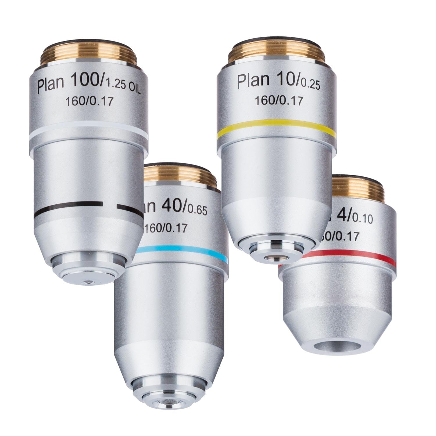
Mounted on the nosepiece, objective lenses are responsible for the initial magnification of the specimen. Most microscopes come with four standard objectives:
- 4× (Scanning): Ideal for locating the specimen on the slide
- 10× (Low Power): General viewing and initial focusing
- 40× (High Dry): Detailed cellular observation
- 100× (Oil Immersion): Maximum resolution for fine structures
Each lens is color-coded for quick identification:
– 4× – Red
– 10× – Yellow
– 40× – Light blue
– 100× – White
As magnification increases, the working distance (space between lens and slide) decreases dramatically—from about 20 mm at 4× to just 0.1 mm at 100×. High-NA (numerical aperture) lenses, like the 100× oil objective, gather more light and deliver sharper, more detailed images.
Oil Immersion Technique Maximizes Resolution at 100×
The 100× oil immersion objective requires a drop of immersion oil (refractive index ~1.515) placed between the lens and the cover slip. This eliminates air gaps that scatter light, maintaining optical continuity and maximizing resolution. Never use this lens dry—images will appear blurry and lack detail. After use, wipe the lens immediately with lens paper, then clean with xylene or commercial lens cleaner to prevent oil residue buildup.
⚠️ Warning: Always rotate the nosepiece to a lower-power objective (like 40× or 10×) before removing the slide to avoid contaminating other lenses with oil.
Nosepiece Allows Quick Objective Switching
The revolving nosepiece (or turret) holds 3–5 objective lenses and allows smooth rotation to switch magnifications. It features click-stop positioning to ensure each lens aligns perfectly with the optical axis. Always rotate the turret ring, not the lenses themselves, to prevent misalignment or damage. Some microscopes have forward- or rear-facing turrets, which can affect viewing comfort depending on user height and posture.
Stage Holds and Positions the Microscope Slide
The stage is the flat platform where you place your microscope slide. It has a central aperture that allows light to pass through the specimen. Two main types exist:
- Plain stage: Uses stage clips to hold slides manually—common in basic models
- Mechanical stage: Offers precise movement via control knobs—essential for high-magnification work
Keep the stage clean and free of debris to avoid blocking light or scratching slides.
Mechanical Stage Enables Precision Slide Movement
A mechanical stage includes two control knobs:
– X-axis knob: Moves the slide left and right
– Y-axis knob: Moves the slide forward and backward
This system allows systematic scanning of the specimen, which is vital when tracking specific cells or preparing photomicrographs. Many models include vernier scales to record exact slide positions for later reference.
Coarse Focus Knob for Initial Focusing
The coarse focus knob is the larger of the two focus controls and moves the stage (or objectives) rapidly. Use it only with 4× and 10× objectives to bring the specimen into rough focus. Never use it with 40× or 100× lenses—doing so risks crashing the lens into the slide, potentially damaging both the lens and the specimen.
🔍 Visual Cue: When focusing, always look from the side to monitor the distance between the lens and the slide.
Fine Focus Knob for Crisp Image Clarity
The fine focus knob makes tiny adjustments—often just 0.002 mm per rotation—to achieve sharp detail. This is essential for high-magnification work (40× and 100×). On most modern microscopes, coarse and fine knobs are coaxial, with the fine knob surrounding the coarse one for easy access during transitions.
Rack Stop Prevents Lens and Slide Damage
The rack stop is a safety feature that limits how high the stage can rise. It prevents the objective lens from colliding with the slide, even if the coarse knob is over-rotated. While usually factory-set, some models allow adjustment—always consult your manual before modifying it.
Illuminator Supplies Consistent Light for Imaging
Located in the base, the illuminator is the microscope’s light source. Modern microscopes use LEDs—energy-efficient, long-lasting, and cool-running. Older or high-end models may use halogen bulbs, which are brighter but generate heat and may require a blue filter to balance color temperature. Some basic microscopes use a mirror to reflect ambient light, but these lack consistent brightness and are limited to well-lit environments.
Brightness Control Optimizes Image Quality
The brightness adjustment knob regulates light intensity. Too much light washes out details; too little makes specimens hard to see. Adjust brightness based on magnification and specimen type. For example, thin, transparent samples need less light than dense or stained tissues.
✅ Best Practice: Start with low brightness and gradually increase to achieve optimal contrast.
Condenser Focuses Light for Maximum Clarity
The condenser, located beneath the stage, collects and concentrates light into a cone that evenly illuminates the specimen. The most common type is the Abbe condenser, capable of up to 1.25 NA, suitable for magnifications up to 1,000×. It’s vertically adjustable via a condenser focus knob. For high magnification, raise the condenser close to the stage (but not touching). For low power, lower it slightly to avoid over-illumination.
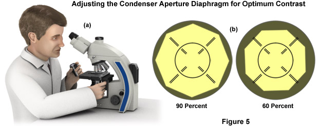
Iris Diaphragm Controls Contrast and Resolution
The iris diaphragm adjusts the width of the light beam passing through the specimen. Closing it increases contrast (useful for transparent specimens) but reduces resolution. Opening it maximizes resolution but may cause glare.
📏 Rule of Thumb: Match the diaphragm opening to the numerical aperture (NA) of the objective lens—this follows Köhler illumination principles for optimal performance.
Total Magnification: How to Calculate It
Total magnification is calculated using the formula:
Total Magnification = Eyepiece Magnification × Objective Magnification
| Objective | Eyepiece (10×) | Total Magnification |
|---|---|---|
| 4× | 10× | 40× |
| 10× | 10× | 100× |
| 40× | 10× | 400× |
| 100× | 10× | 1,000× |
Maximum useful magnification is about 1,500×—beyond that, images become larger but not clearer, a phenomenon known as empty magnification.
Best Practices for Use and Maintenance
- Start with 4× objective to locate and center the specimen
- Use coarse focus only at low power; switch to fine focus for 40× and 100×
- Clean lenses with lens paper only—never use fingers, cloth, or tissues
- Carry with two hands: one on the arm, one under the base
- Cover the microscope when not in use to prevent dust buildup
- Store in a dry, clean environment away from chemicals
Mastering the parts of a compound light microscope and their functions transforms you from a casual observer into a skilled microscopist. Each component—from the base to the eyepiece, from the condenser to the fine focus knob—plays a vital role in delivering sharp, detailed images. By understanding how they work together, you can optimize settings for any specimen, avoid common errors, and maintain your instrument for years of reliable use. Whether you’re a student learning biology or a researcher analyzing cellular details, this knowledge is the foundation of effective microscopy.