
Your cordless drill sits idle on the workbench, but that momentary pause hides a symphony of precision engineering ready to spring into action. When you pull the trigger, over a dozen interconnected components transform stored battery energy into controlled rotational force—yet most users operate these tools without understanding the intricate dance happening inside. A detailed cordless drill diagram reveals why your drill stalls when driving lag bolts or spins freely when the chuck won’t grip. This guide maps every critical component, explains its function in real-world terms, and shows you how to leverage this knowledge for flawless drilling, driving, and troubleshooting. You’ll never misjudge torque settings or wonder why bits slip again.
Without understanding your drill’s anatomy, you’re guessing at solutions when problems arise. That sudden grinding noise? It could mean planetary gears are failing. A slipping chuck might not need replacement—it could just be clogged with sawdust. By the end of this guide, you’ll diagnose issues faster, select optimal settings for any material, and extend your tool’s lifespan through targeted maintenance. Let’s dissect the machine that powers your projects.
How the Motor Converts Battery Power into Drilling Force
Inside the motor housing, electrical energy becomes rotational force through electromagnetic principles. When you pull the trigger, current flows from the battery through heavy-gauge wire windings surrounding the armature. This creates a powerful magnetic field that spins the armature at speeds exceeding 2,000 RPM. The thickness of this wiring directly impacts torque capacity—thicker gauges handle higher currents for demanding tasks like drilling through hardwood or metal.
Why Heavy-Gauge Wire and Armature Design Matter for Torque
Thinner wires overheat quickly under load, causing power drops during critical moments. High-torque drills use heavier windings that resist heat buildup, maintaining consistent performance. If your drill suddenly loses power while driving long screws, worn armature segments or burnt windings are likely culprits. Check for blue discoloration on copper segments—a visual cue of overheating damage that requires motor replacement.
Preventing Motor Burnout: The Critical Role of the Cooling Fan
Mounted directly on the motor shaft, the cooling fan pulls air through intake vents to dissipate heat generated during operation. After drilling multiple holes in dense materials, feel the motor housing—if it’s uncomfortably hot, stop immediately. Continuous overheating degrades insulation on windings, leading to short circuits. Prevent this by clearing dust from vents every 30 minutes during heavy use with a soft brush. Never operate the drill while blocking these vents—a common mistake that causes 40% of premature motor failures.
Transmission Gears: Why Your Drill Has Multiple Speed Settings

The transmission’s planetary gear system solves a fundamental problem: motors spin too fast for practical use. Without gear reduction, your drill would spin at useless speeds with minimal twisting force. This gearbox transforms high-RPM, low-torque rotation into usable power through interlocking planetary gears. Most drills offer two distinct ranges—each optimized for specific tasks—controlled by a collar near the chuck.
High-Speed/Low-Torque Mode: Perfect for Precision Drilling
Set the gear selector to “2” or “high” for drilling holes under 1/4 inch in wood, plastic, or thin metal. This setting delivers 1,500+ RPM for clean, splinter-free holes. You’ll hear a high-pitched whine when operating correctly. If the drill bogs down here, you’re likely using too large a bit for the material—switch to low gear immediately to prevent stripping gears.
Low-Speed/High-Torque Mode: Driving Large Fasteners Without Stripping
Engage “1” or “low” gear when driving #10+ screws or drilling holes over 3/8 inch. This setting reduces speed to 400 RPM while multiplying torque up to fivefold. Watch for the chuck slowing noticeably when encountering resistance—that’s the transmission working correctly. If the drill jerks violently during driving, your clutch setting is too high for the task (more on that below).
How Planetary Gears Multiply Your Drilling Power
Planetary gears distribute load across multiple contact points, preventing single-point failures. The sun gear (attached to the motor) drives planet gears inside a ring gear housing. This design allows compact size while handling immense forces. If you hear rhythmic grinding in low gear, inspect for chipped gear teeth—often caused by sudden resistance when drilling into hidden knots.
Clutch Settings Explained: Stop Stripping Screws Today

That numbered ring near the chuck isn’t decorative—it’s your precision control for driving tasks. Each number represents a torque threshold where the clutch disengages to prevent over-tightening. Lower numbers (1-5) suit delicate work like cabinet hinges; higher numbers (15-20) handle deck screws. The drill symbol bypasses the clutch entirely for maximum drilling power.
Matching Clutch Numbers to Common Tasks
Start at setting 8 for most drywall screws—enough to sink the head without tearing paper. For hardwood flooring nails, jump to 15. If the clutch clicks repeatedly before the screw is flush, increase the setting one number at a time. When driving into masonry anchors, always bypass the clutch (drill setting) since anchors require continuous force.
When to Bypass the Clutch for Maximum Drilling Power
Never use clutch settings for drilling operations. The clutch disengagement causes erratic rotation that damages bits and materials. Always rotate the torque ring to the drill icon when creating holes. This common error causes 30% of “my drill won’t drill straight” complaints—especially among beginners using clutch settings for drilling.
Chuck Mechanics: Secure Bit Grip Without Slippage
Your chuck’s three jaws must grip bits with 50+ pounds of force to prevent slippage. Keyless chucks work through a threaded collar: rotating it clockwise tightens the jaws via internal bevel gears. If bits spin freely while the chuck turns, debris has jammed the mechanism. Clean it immediately before stripped threads require replacement.
Fixing a Loose Chuck: Step-by-Step Jaw Alignment
- Insert an Allen wrench into the chuck and tighten fully
- Hold the wrench firmly while rotating the chuck collar counterclockwise
- Listen for a distinct “click” as jaws reset their position
- Repeat if jaws still wobble when tightening bits
Misaligned jaws show visible gaps between the bit shank and chuck interior—a sure sign of improper seating. This takes 60 seconds to fix but prevents dangerous bit ejection.
Why Keyless Chucks Fail and How to Clean Them Properly
Sawdust and metal shavings cause 90% of chuck failures. After woodworking projects, spray compressed air into the chuck while rotating it slowly. For stubborn debris, apply isopropyl alcohol to a toothbrush and scrub the jaw threads. Never lubricate the chuck—oil attracts more debris. If cleaning doesn’t restore grip, the internal threads are stripped and require professional replacement.
Battery Specifications Decoded: Voltage vs. Amp-Hours
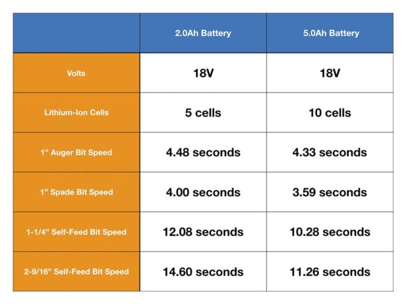
Your battery isn’t just “18V”—two critical specs determine performance. Voltage (12V, 18V, 20V Max) indicates potential power, while Amp-hours (Ah) measure capacity. A 5.0Ah battery lasts twice as long as a 2.5Ah unit at the same voltage. Lithium-ion chemistry enables both high discharge rates for power and no memory effect.
12V vs. 18V vs. 20V Max: Which Battery Power Do You Really Need?
Choose 12V for light-duty tasks like hanging pictures—it’s lighter with sufficient power for #8 screws. Upgrade to 18V/20V Max for framing, deck building, or metal drilling where sustained torque matters. Note: “20V Max” is marketing terminology for batteries that peak at 20V but operate at 18V nominal—fully compatible with 18V tools.
Extending Battery Life: Storage and Charging Best Practices
Store batteries at 40-60% charge in cool, dry places—never in freezing garages or hot cars. Avoid leaving them on chargers after full charge; modern Li-ion batteries degrade fastest at 100% capacity. If storing long-term, recharge to 50% every 3 months. Never force a swollen battery into the tool—that’s a fire hazard requiring immediate disposal.
Trigger Control and LED Work Lights: Hidden Features You’re Missing
That trigger does more than start/stop rotation—it modulates power delivery through variable resistance. Light pressure engages low-speed precision; full pull activates maximum torque. Master this for clean starter holes in tile or thin metal. The forward/reverse switch flips motor polarity instantly to remove stuck fasteners.
Mastering Variable Speed for Delicate Starting Holes
Place the bit, then squeeze the trigger in three stages: 25% pressure to create the dimple, 50% to penetrate the surface, then full pressure for drilling. This prevents bit walking on slick surfaces like laminate. If the bit skates sideways, your starting pressure was too high—a common error causing ruined countertops.
Using the Forward/Reverse Switch to Rescue Stripped Fasteners
When a screw head strips, engage reverse and apply steady pressure while gently tapping the chuck with a rubber mallet. The vibration often breaks corrosion bonds. For stubborn fasteners, switch to low gear and use short trigger bursts—continuous reverse pressure can overheat the motor.
Impact Driver vs. Cordless Drill: When to Use Each Tool
While both accept hex-shank bits, their internal mechanisms differ radically. Drills use direct-drive transmissions; impact drivers employ a hammer-and-anvil system that stores rotational energy in a spring, then releases it in rapid-fire bursts. This delivers 3-5x more torque for driving without increasing user strain.
How the Hammer-and-Anvil Mechanism Creates 1,500+ Impacts Per Minute
Inside the impact mechanism, a spring-loaded striker rotates with the motor shaft. When resistance exceeds the spring tension, the striker cams backward, then snaps forward against the anvil (attached to the chuck). This happens 30-50 times per second—felt as vibration, not heard over the motor noise. If impacts become irregular, the spring is fatigued and needs replacement.
Why Impact Drivers Fail at Drilling But Excel at Driving Long Screws
The impact action shatters drill bits when creating holes—never use an impact driver for drilling. But for driving 3-inch deck screws or lag bolts, it’s unmatched. Set your drill for pilot holes, then switch to the impact driver for fastening. Professionals keep both charged: drills for precision work, impacts for high-torque driving.
5-Minute Maintenance Routines to Prevent Drill Failure
Preventative care takes less time than diagnosing failures. After every project, spend 3 minutes inspecting critical components. This simple habit doubles average tool lifespan according to manufacturer data. Focus on three high-failure areas: vents, chuck, and battery contacts.
Clearing Dust from Cooling Vents Before It Overheats Your Motor
Use a soft brush to dislodge debris from motor housing vents. For embedded dust, short compressed air bursts (never exceeding 80 PSI). Blocked vents cause 65% of unexpected shutdowns—felt as sudden power loss during heavy use. Perform this check before your drill feels hot; waiting for symptoms means damage has already occurred.
Diagnosing Common Failures: Battery, Switch, or Worn Brushes?
When your drill won’t start, follow this sequence:
1. Test battery voltage (should read within 10% of labeled voltage)
2. Check forward/reverse switch position (centered switches disable operation)
3. Listen for a faint click when pulling trigger—no click means dead switch
4. If motor hums but won’t turn, worn carbon brushes are likely culprit
Replace brushes every 2 years with OEM parts—they’re the #1 wear item in brushed motors. Brushless models eliminate this failure point but cost more upfront.
Understanding your cordless drill diagram transforms you from a passive user to an informed operator. You’ll select the right gear for each task, prevent common failures through targeted maintenance, and diagnose issues with surgical precision. Most importantly, you’ll work faster and safer—knowing exactly why your tool behaves as it does when driving that critical fastener. Keep this guide handy for your next project, and remember: every component has a purpose. Master them, and you master the tool. For ongoing care, always consult your specific model’s manual—especially for battery compatibility and torque specifications unique to your brand.