If your night vision monocular isn’t working, don’t assume it’s beyond repair. Most failures aren’t due to a dead image intensifier tube—instead, they stem from simple power issues like dead batteries, corroded contacts, or a faulty voltage regulator. Whether your device won’t power on, shows no image despite working IR, or flickers unpredictably, this guide delivers real-world fixes backed by user-tested diagnostics and electrical troubleshooting. You’ll learn how to test circuits, identify failed components, and even rebuild the high-voltage supply using repurposed electronics—all without expensive tools. By the end, you’ll know exactly what’s broken and whether to repair, replace, or salvage your unit.
Check Power Source Before Opening the Device
Start with the most common cause: power delivery. A night vision monocular not working often comes down to something as basic as weak or improperly installed batteries.
Test Battery Voltage and Confirm Polarity
Use a multimeter to measure battery output. Most monoculars run on 3V from CR123 or AA lithium cells. If voltage reads below 2.4V, replace them—even if they’re labeled “new.” Some off-brand batteries lose charge quickly or fail prematurely. Always use high-quality lithium cells for reliable performance.
Double-check polarity against markings inside the battery compartment. Reversed batteries may not blow a fuse but can prevent startup, especially in sensitive analog units like ATN or Gen 1 devices. One user reported a fully functional monocular that wouldn’t turn on—until they discovered a single reversed battery.
Clean and Inspect Battery Contacts
Corrosion or oxidation on metal contacts is a leading cause of failure, especially in second-hand or long-stored units. Remove the batteries and examine both the housing terminals and the internal PCB contacts. Look for discoloration, greenish residue (from alkaline leakage), or dull gray film (oxidation).
Clean all surfaces with isopropyl alcohol (90% or higher) and a cotton swab. For stubborn buildup, use electrical contact cleaner and a soft-bristled brush. Even if contacts look clean, a thin oxide layer can block conductivity—wiping them thoroughly often restores function.
Pro Tip: After cleaning, test continuity between the battery spring and the PCB trace with a multimeter. No connection? There may be a broken trace or loose wire.
Verify Power Switch Operation
Cycle the power switch 5–10 times to dislodge any internal oxidation. Some switches develop high resistance over time, causing intermittent power. Use a multimeter in continuity mode: press the switch and listen for a beep. No response? The switch may be worn out or internally damaged.
If the device powers intermittently when you wiggle the switch, it’s likely failing. You can temporarily bypass it by shorting the two switch contacts with a screwdriver (only while testing) to confirm if the rest of the circuit works.
Diagnose Low-Voltage Circuit Activity Without Tools

If the monocular still won’t turn on, look for signs that power is reaching the internal circuitry. These tests help isolate whether the problem lies in power delivery or deeper electronics.
Look for IR Illuminator Glow Using a Phone Camera
Press the IR button and point your smartphone camera at the front of the device. Many phone sensors detect near-infrared light invisible to the human eye. If you see a faint red or white glow, the low-voltage circuit is alive—meaning:
- The battery is delivering power
- The switch is functional
- The microcontroller (if digital) is active
This narrows the fault to the high-voltage supply or image intensifier tube. If there’s no glow, the issue is likely earlier in the power chain: battery, switch, or regulator.
Listen for the High-Pitched Oscillator Whine
Gen 1 and Gen 2 analog monoculars often emit a faint ~20–50 kHz whine when powered. This sound comes from the oscillator driving the high-voltage multiplier. Turn off ambient noise and cup your hand around the device to amplify the sound.
Hearing a whine means the oscillator is running—so the fault is downstream, such as a broken trace, failed capacitor, or disconnected tube. No sound? The oscillator, driving transistor, or regulator may be dead.
Try the LED Test (No Multimeter?)
If you don’t have a multimeter, use a standard LED to test low-voltage flow. Insert the LED across the battery output and ground (e.g., on the PCB pads). Press the power switch. If the LED lights up, power is reaching the board.
⚠️ Warning: This only confirms basic power delivery. It doesn’t test high-voltage circuits or the image tube.
Open and Inspect Internal Components
If basic checks fail, disassemble the unit. Most monoculars have 2–4 screws, often hidden under rubber grips or lens caps. Use a plastic pry tool to avoid scratching.
Check for Loose or Broken Wires
Once open, inspect the battery compartment wiring. A known failure point—especially in MNVK Gen2 and older models—is a loose or desoldered wire at the battery terminal. Look for:
- Wires detached from the PCB
- Cracked solder joints
- Broken spring contacts
Use a magnifier if needed. Re-solder any loose connections with rosin-core solder. Secure wires with a dab of hot glue to prevent future stress.
Case Study: An MNVK monocular showed no power despite fresh batteries. Upon opening, one battery lead was completely disconnected. Re-soldering it restored full function.
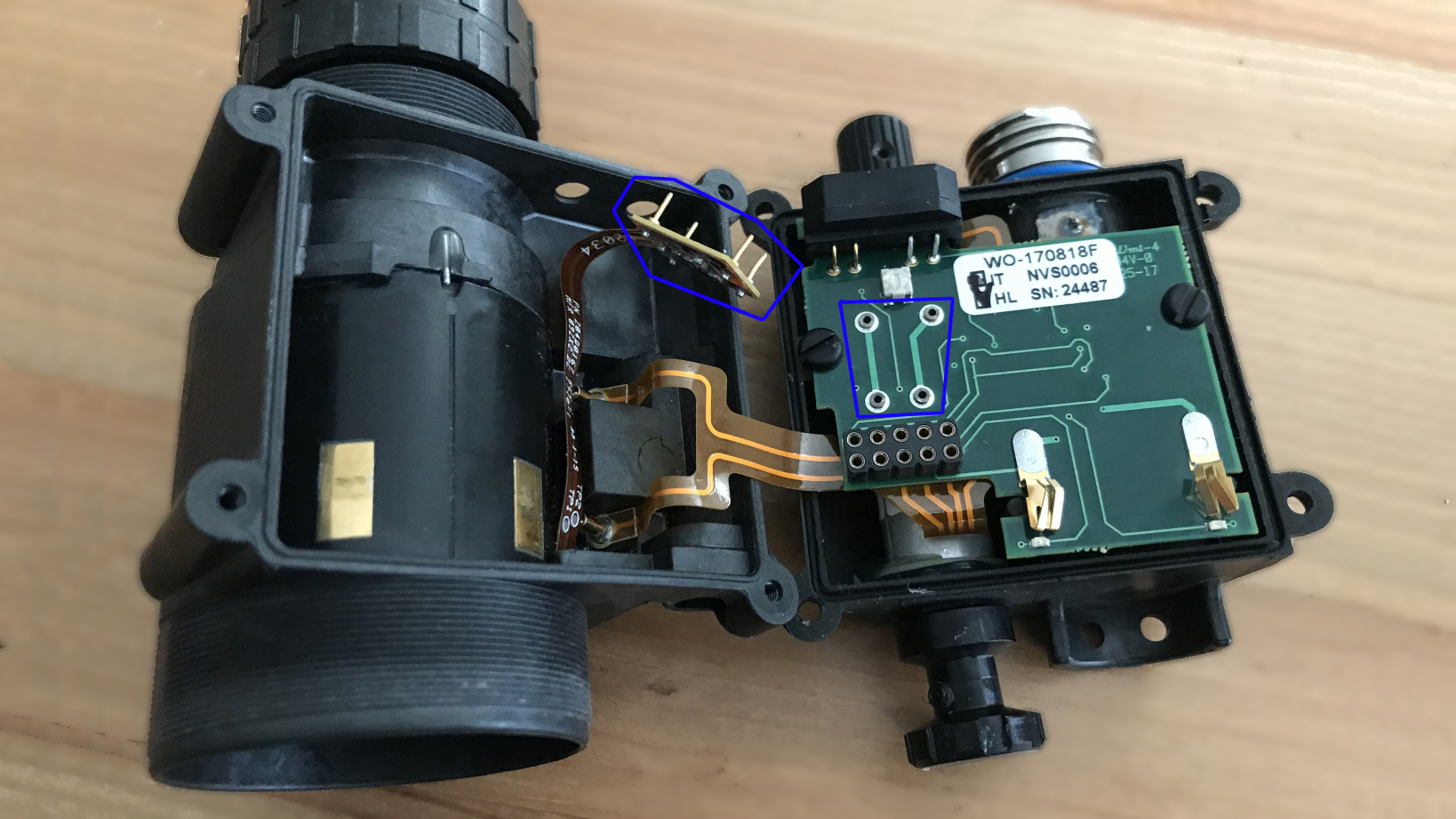
Examine the Voltage Regulator for Misreplacements
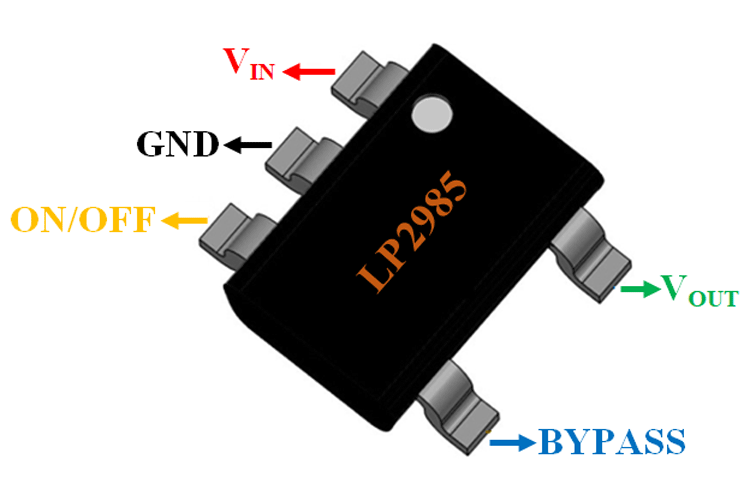
Locate the voltage regulator—often labeled LP2985, GP7U, or similar. This chip converts battery voltage to stable 3V for the circuit. A common failure is someone replacing it with an incompatible model.
Check:
– Is the correct model installed?
– Are pins connected properly?
A frequent mistake: installing an LP2985 with the On/Off pin tied through an inductor to the output, or shorting the Bypass pin. This prevents the regulator from activating.
Fix: Desolder the faulty chip using a rework station or soldering iron with desoldering braid. Install the correct regulator with proper pin configuration:
– Input → battery
– Ground → common ground
– Output → main PCB
– On/Off → switch control
– Bypass → capacitor to ground (per datasheet)
Glue the new regulator to a heatsink if available. Even small regulators can overheat under load.
Test High-Voltage Circuit and Image Tube
If low-voltage circuits are functional but there’s still no image, the fault is likely in the high-voltage (HV) supply or image intensifier tube.
Use the Neon Bulb Test to Detect AC Voltage
You don’t need a high-voltage probe. A small neon bulb (like NE-2) can detect AC from the oscillator. Touch the leads to the input of the Cockcroft-Walton multiplier (usually two thin wires going to the tube).
If both electrodes glow, AC is present—the oscillator is working. No glow? The oscillator or driving transistor is dead.
This test is safe and effective for Gen 1 devices where the HV circuit outputs AC before rectification.
Measure Key Electrical Benchmarks
With a multimeter, check:
– Battery voltage: ~2.4–3V
– IR LED voltage drop: ~1.7V
– Image tube current draw: ~10 mA
– IR LED current draw: ~80 mA
If the IR LED draws current but the tube doesn’t, the HV circuit isn’t delivering power.
Diagnose Image Intensifier Tube Failure
Gen 1 tubes degrade over time—even when unused. Typical lifespan: 2–5 years. Symptoms of failure:
– No image despite power and IR glow
– Dim or flickering image that worsens over time
– Partial screen glow (indicates partial HV delivery)
Note: Some users report a “whine” and working IR but no image—classic signs of a dead tube or failed HV multiplier.
Repair or Replace HV Power Supply
If the HV circuit is dead, rebuild it using common electronics.
Use a CCFL Inverter for Reliable AC Output
CCFL inverters from old laptops output 2,000–3,000V AC—perfect for image tubes. They’re efficient and low-draw.
Steps:
1. Disconnect original HV circuit
2. Connect inverter input to 3V line (after regulator)
3. Connect output to tube’s anode and cathode
4. Ground the inverter chassis
You can cascade two inverters to reach ~6,000V if needed.
Repurpose a Disposable Camera Flash Circuit
Harvest the flash board from a disposable camera. It generates ~300V DC, but most tubes need AC.
Fix: Bypass the rectifier diode to access AC from the transformer. Add a current-limiting resistor and a 50kΩ pull-down resistor to prevent charge buildup.
Build a 555 Timer Oscillator
For full control:
– Use a 555 timer IC
– Drive a MOSFET (e.g., IRF510)
– Connect to a small HV transformer
– Add a 50kΩ pull-down resistor
Adjust frequency with R/C values to match tube requirements (~20–50 kHz).
Try a ZVS Driver or Slayer Exciter
For higher efficiency:
– ZVS Circuit: Delivers ~8,000V with low heat. Use polypropylene capacitors.
– Slayer Exciter: Simple Tesla-style circuit using a relay coil.
⚠️ Safety First:
– Use insulated tools
– Wear rubber gloves and eye protection
– Work on non-conductive surface
– Use a 0.5–1 MΩ resistor in series to limit current
Model-Specific Fixes and Tips
Know your model before troubleshooting.
ATN Monoculars: Cover the Bright Light Sensor
ATN devices won’t start unless the bright light sensor (near objective lens) is covered. If your unit won’t turn on:
– Cover the sensor with tape or your finger
– Press power
Also:
– Never use in daylight—can permanently damage the tube
– Average runtime: 40 hours with lithium batteries
– Warranty: 2 years on analog models
MNVK Gen2: Fix Loose Battery Contacts
Common issue: flimsy internal battery contacts. If IR works but no image:
– Open battery compartment
– Check for loose solder joints
– Re-solder any disconnected wires
One user restored function by fixing a single broken connection.
Prevent Environmental Damage
Avoid bright light exposure—always cap the lens until dark. Manage humidity with silica gel packs and anti-fog sprays. Store in a temperature-stable environment.
Final Note: A night vision monocular not working is rarely terminal. Loose connections, bad regulators, and corroded contacts cause most failures—not dead tubes. With basic tools and this guide, you can revive many “bricked” units. Always start simple, test methodically, and prioritize safety with high-voltage circuits. Whether you fix it or harvest parts, you win either way.